Chapter 5
Application Notes
V  Maximum Query / Response Parameters
V Estimating Serial Transaction Timing
V Application Notes for the 584 and 984A / B / X
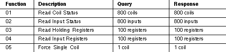
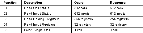
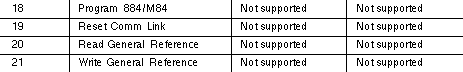
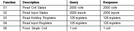
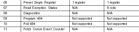
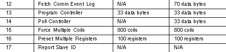
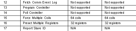
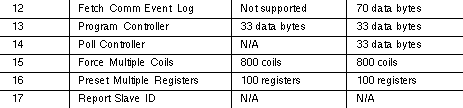
5.1 Maximum Query / Response Parameters
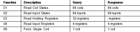
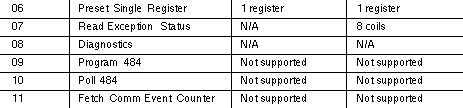
The listings show the maximum amount of data that each
controller can request or send in a master query, or return in a
slave response. All function codes and quantities are in decimal.
184/384


484
These values are for an 8K controller. See the 484 User's Guide for
limits of smaller controllers.
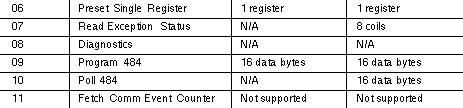
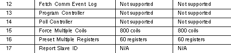
584
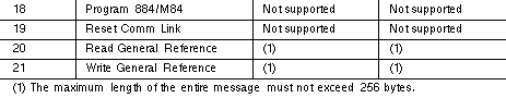
884


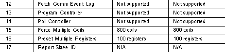

M84
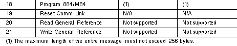
984


5.2 Estimating Serial Transaction Timing
The following sequence of events occurs during a Modbus serial
transaction. Letters in parentheses ( ) refer to the timing notes at
the end of the listing.
1 The Modbus master composes the message.
2 The master device modem RTS and CTS status are checked.
(A)
3 The query message is transmitted to the slave. (B)
4 The slave processes the query message. (C, D)
5 The slave calculates an error check field. (E)
6 The slave device modem RTS and CTS status are checked. (A)
7 The response message is transmitted to the master. (B)
8 The master application acts upon the response and its data.
Timing Notes
A If the RTS and CTS pins are jumpered together, this time is
negligible. For J478 modems, the time is about 5 ms.
B Use the following formula to estimate the transmission time:
Time (ms) = 1000 * (character count) * (bits/character)
Baud Rate
C The Modbus message is processed at the end of the controller
scan. The worst-case delay is one scan time, which occurs if the
controller has just begun a new scan. The average delay is half
the scan time.
The time allotted for servicing Modbus ports at the end of the
controller scan (before beginning a new scan) depends upon the
controller model. Timing for each model is described on the next
page.
For 484 controllers the time is approximately 1.5 ms. The Modbus
port is available on a contention basis with any J470 / J474 / J475
that is present.
For 584 and 984 controllers the time is approximately 1.5 ms for
each Modbus port. The ports are serviced sequentially, starting
with port 1.
For 184 / 384 controllers the time varies according to the amount of
data being handled. It ranges from a minimum of 0.5 ms to a
maximum of about 6.0 ms (for 100 registers), or 7.0 ms (for 800
coils). If a programming panel is currently being used with the
controller, the Modbus port is locked out.
D Modbus functions 1 through 4, 15, and 16 permit the master to
request more data than can be processed during the time alloted
for servicing the slave's Modbus port. If the slave cannot process
all of the data, it will buffer the data and process it at the end of
subsequent scans.
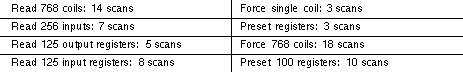
The amount of data that can be processed during one service
period at the Modbus port is as follows:
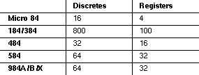


Note: 984-X8X refers to 984 slot mount models (984-385, -685,
etc).
For the 884, the processing time for multiple data is as follows:
E LRC calculation time is less than 1 ms. CRC calculation time is
about 0.3 ms for each eight bits of data to be returned in the
response.
5.3 Notes for the 584 and 984A / B / X
Baud Rates
When using both Modbus ports 1 and 2, the maximum allowable
combined baud rate is 19,200 baud.
Port Lockups
When using ASCII, avoid sending zero-data-length messages or
messages with no device address. For example, this is an illegal
message: